Fresh Wharf, London — MEP BIM and drawing production
Retrofit of an 11-storey office building on Lower Thames Street in the City of London: 120,000 sq ft of workspace and 25,150 sq ft of terraces on the north bank of the Thames, with the existing frame retained and reworked rather than demolished.
- Location
- United Kingdom
- Our services
- MEP BIM modelling · Multidisciplinary coordination · Drawing production
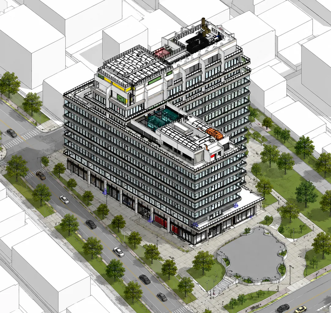
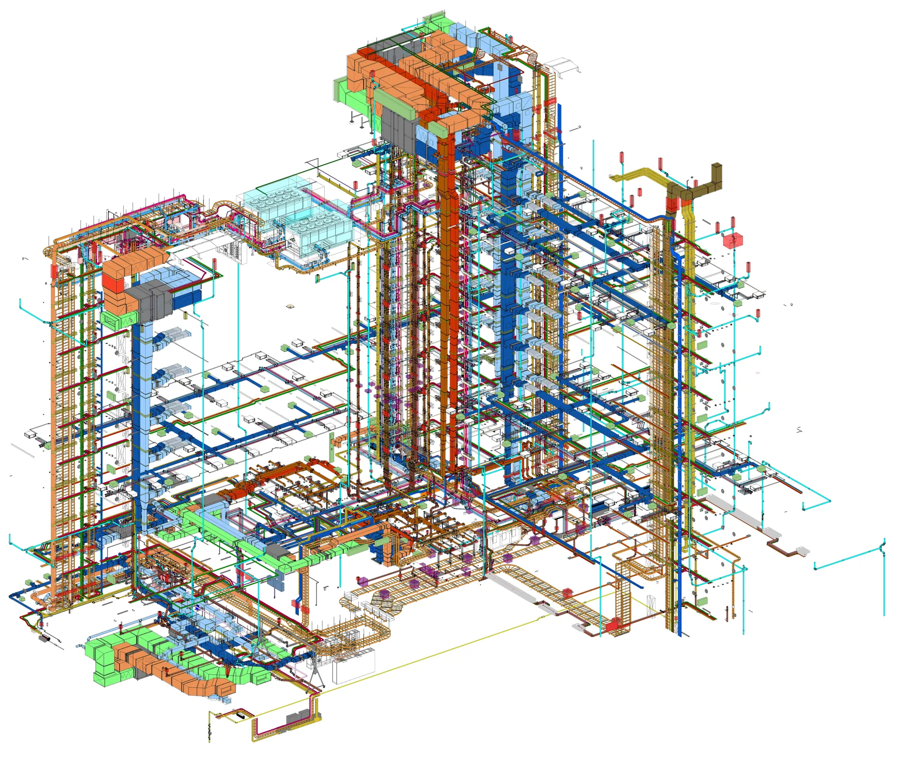
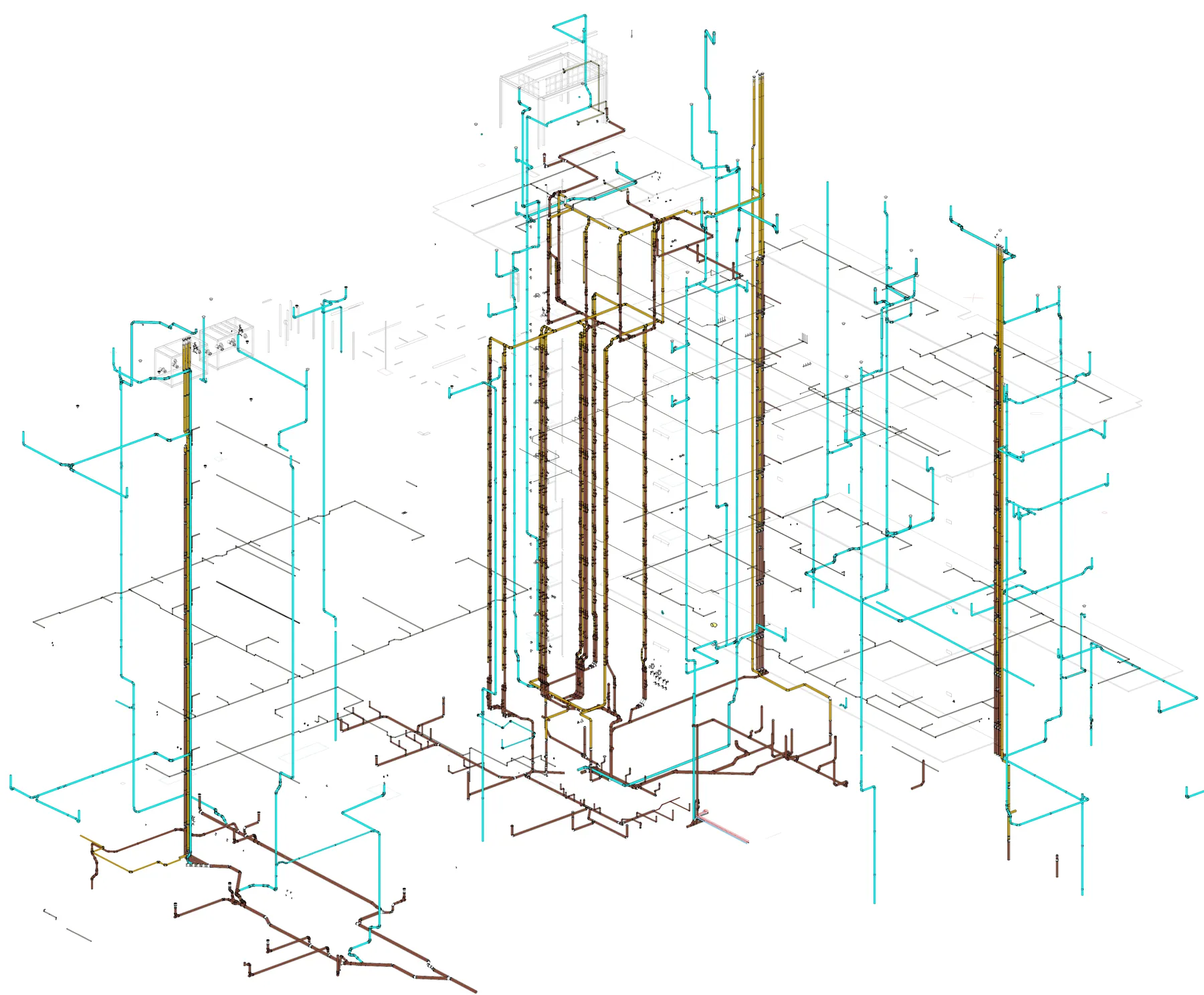
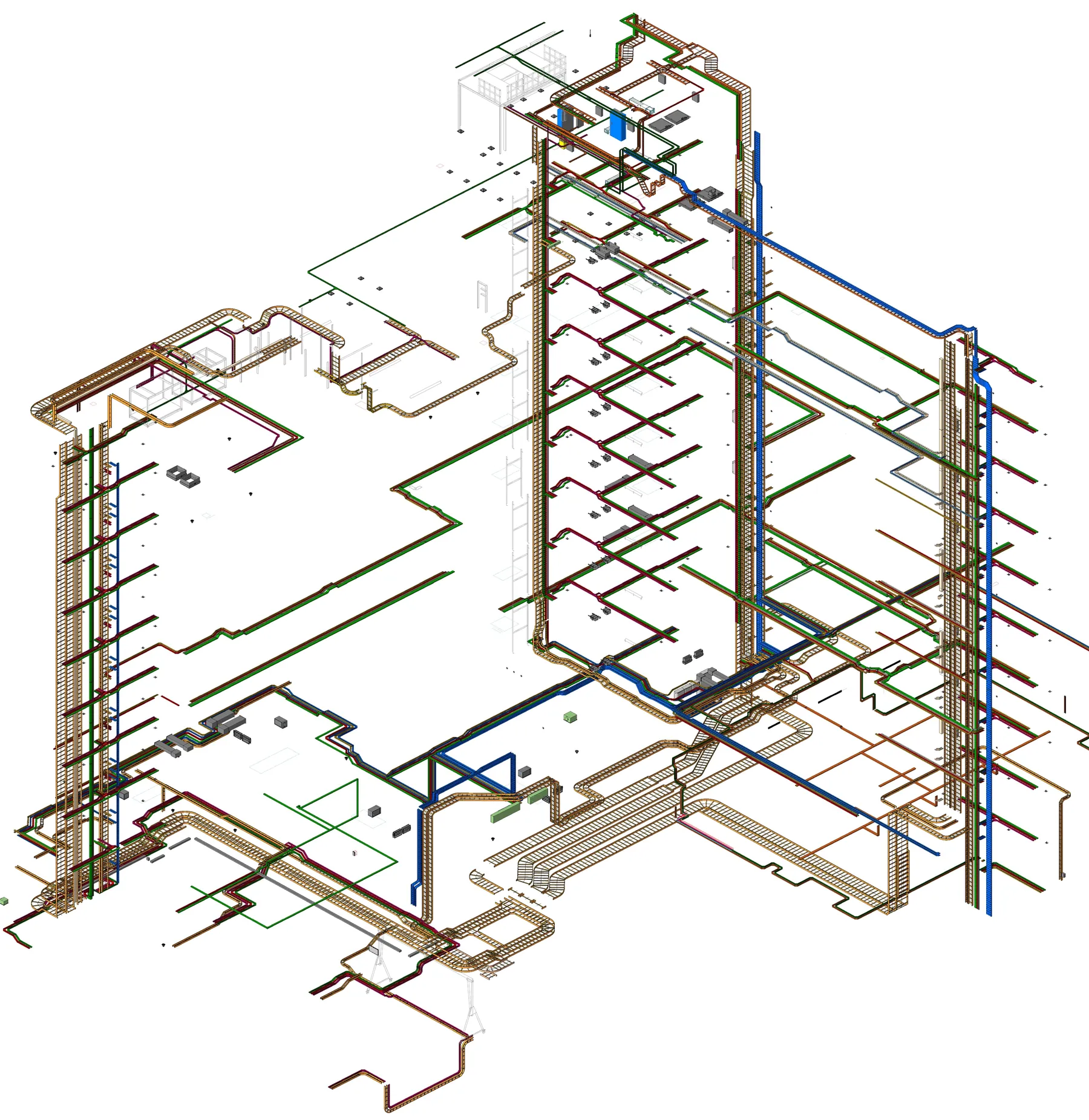
We delivered the multidisciplinary MEP BIM — mechanical, electrical and public health modelled as separate discipline models and federated against the retained structure and the architectural model — spatially coordinated and clash-resolved within the existing floor-to-floor zones, with the drawings, sections and builder’s work openings issued from it.
The building targets BREEAM ‘Outstanding’, WELL Platinum, NABERS 4.5-star and WiredScore Platinum.
Services into a retained frame
A retained frame fixes the constraints before the services start. Floor-to-floor heights, slab openings, core and riser positions are set by the building that already exists, and the ceiling void left for distribution is whatever the frame allows. Every duct, pipe, tray and terminal is modelled inside that zone against the retained structure, so the space each system needs is proved against the building as it will be and not against a nominal void.
Terraces across the building
25,150 sq ft of external terrace changes the services on the floors that carry it. Drainage, power and lighting run out to open areas, plant and distribution are routed around the terrace footprint, and the transitions between inside and outside are modelled where they occur — so the routes are resolved on the floors that give up internal area to them.
Performance carried by the services
The certification targets are settled largely in the services: ventilation rates, air and water quality, thermal comfort and lighting for the wellbeing standard; metering, plant selection and system efficiency for the energy ratings; riser capacity, resilience and diverse entry routes for the connectivity standard. Each is a physical demand on plant space, risers and distribution, and each is carried in the model.
Drawings out of the model
Plans, sections, riser diagrams, plant room layouts and builder’s work openings issued from the model rather than drawn beside it, so the set moves with the coordination instead of trailing behind it.